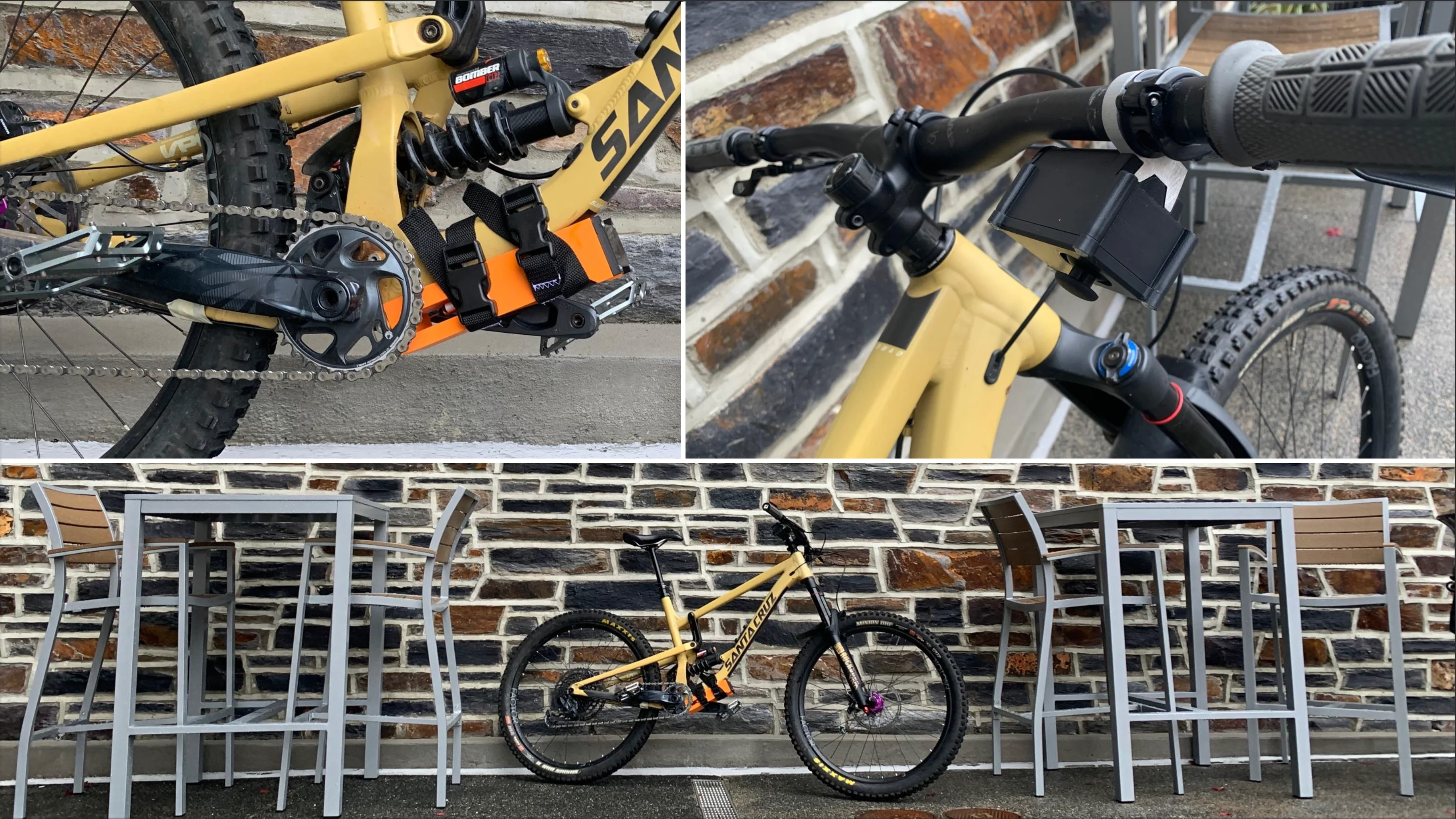
Wireless. Reliable. Universal.

Existing wireless shifters are VERY expensive ($1500+) and inherently vulnerable to impacts.
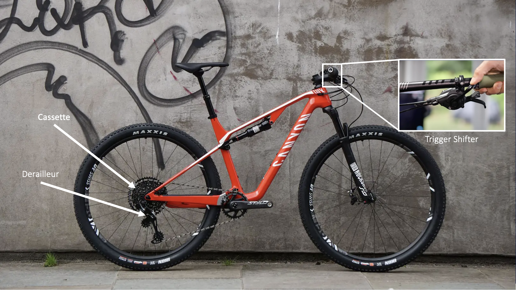
Mechanical shifting systems are only compatible with one gear configuration (1x12 for example).
Shift distance between specific gears cannot be adjusted with a mechanical system.
Mechanical shift cables are ugly.

Universal
Durable
Reliable
Easy to Use
Is the Linear Actuator I specced strong and fast enough to deliver responsive shifting under load?
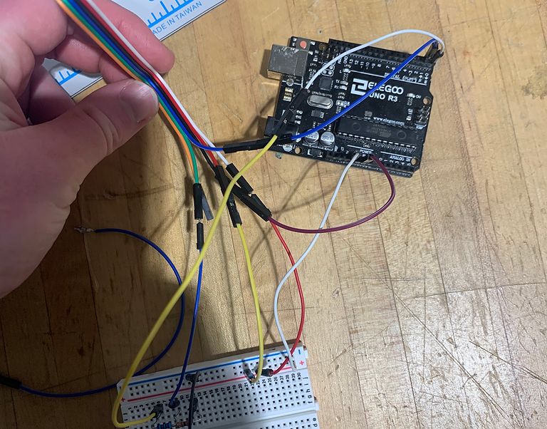
Originally I started with HC-05 Bluetooth modules, which continuously transmit data. I quickly realized that not only was the wiring overly complex but the continuous transmission of data was not necessary in this application. I then decided to make the change to Arduino Nano 33 BLE Sense microcontrollers, which have integrated low energy Bluetooth, perfect for irregular communication.
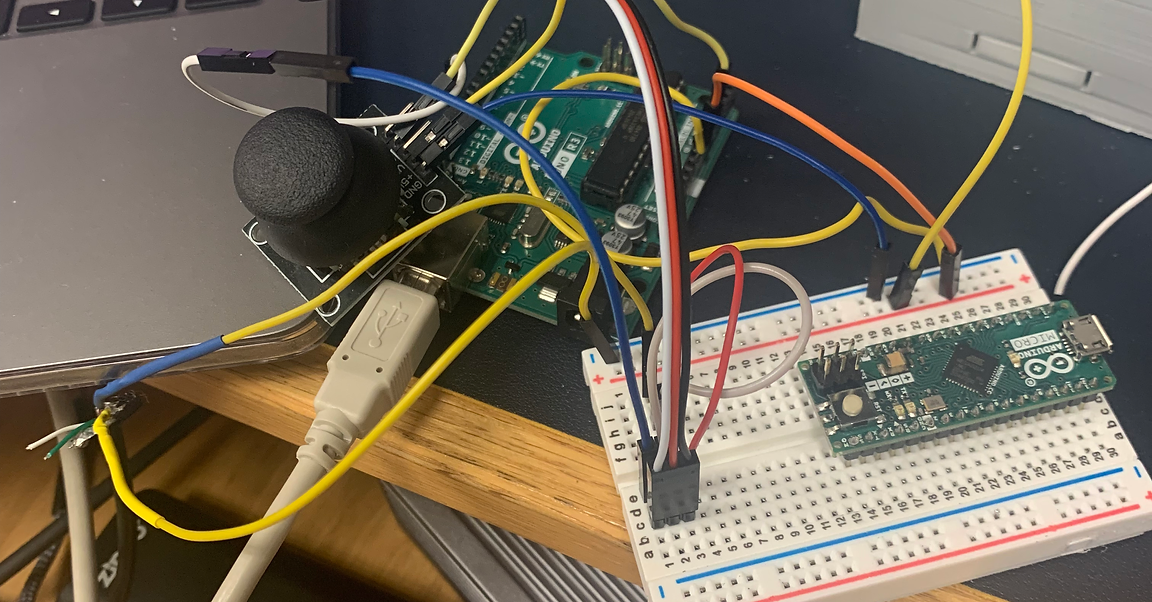

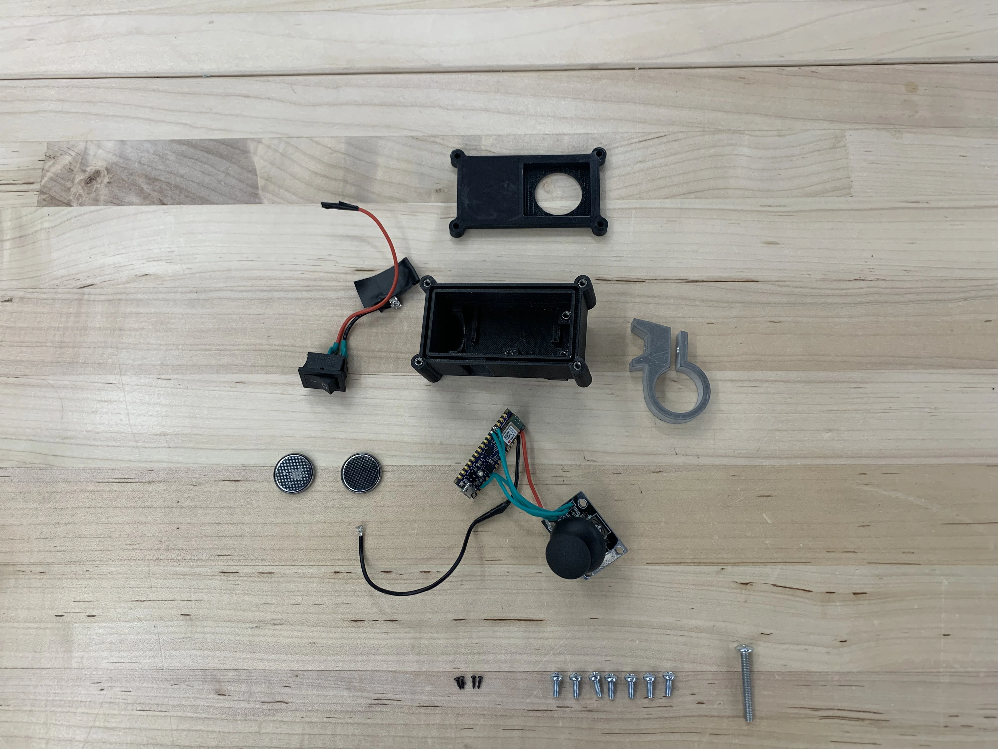
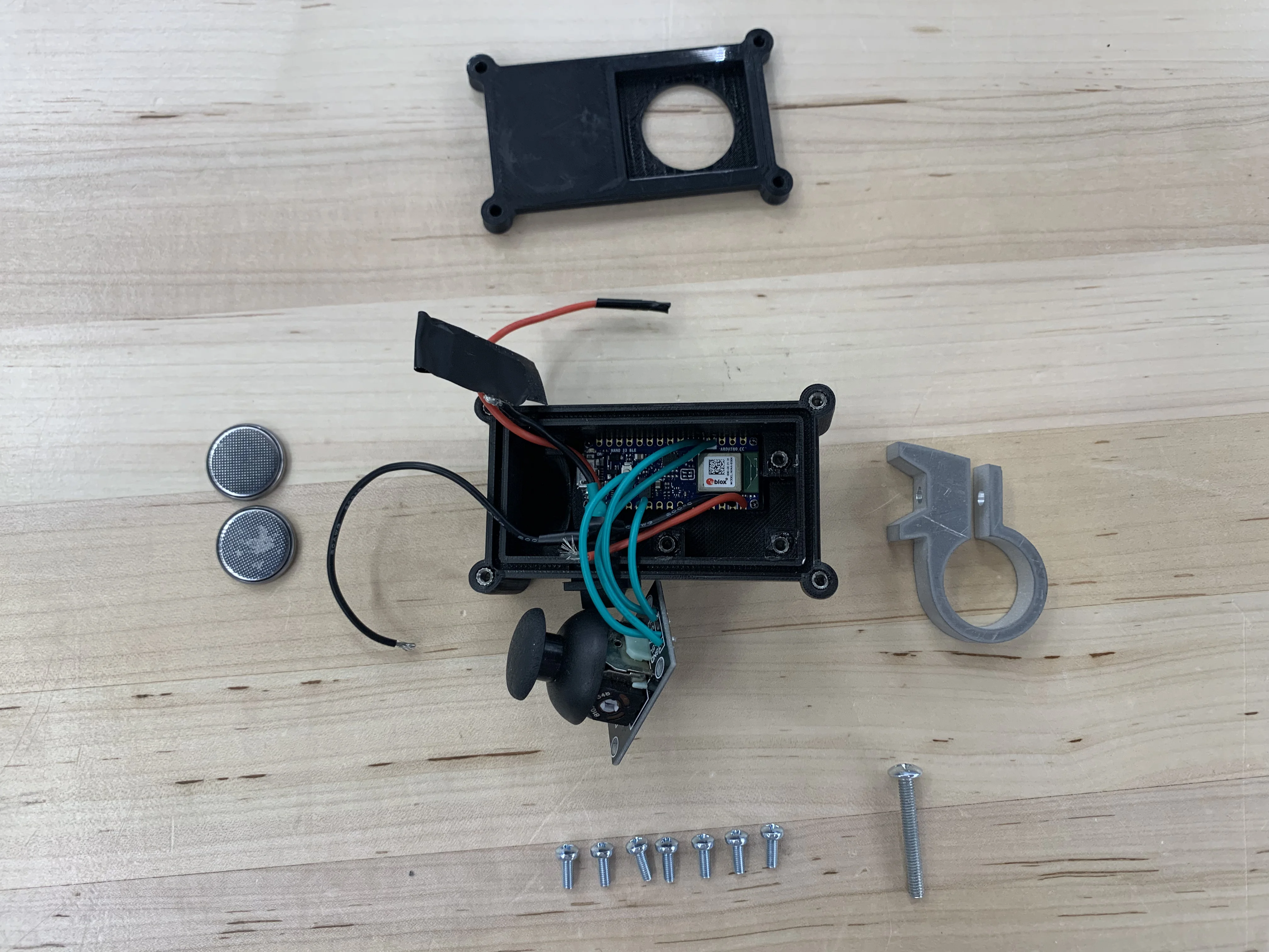
Any good shifter should allow for the user to keep one finger on the brake lever and their thumb on the shifter. I settled on a joystick to accomplish this and give the shifter a fun feel. The original shifter clamp I prototyped was made from two half circles but I realized I could make it all one piece with a flexure, reducing part count and weight. A final change was the transition from two 2032 coin batteries to the same to Li-ion AA batteries found in the actuator.
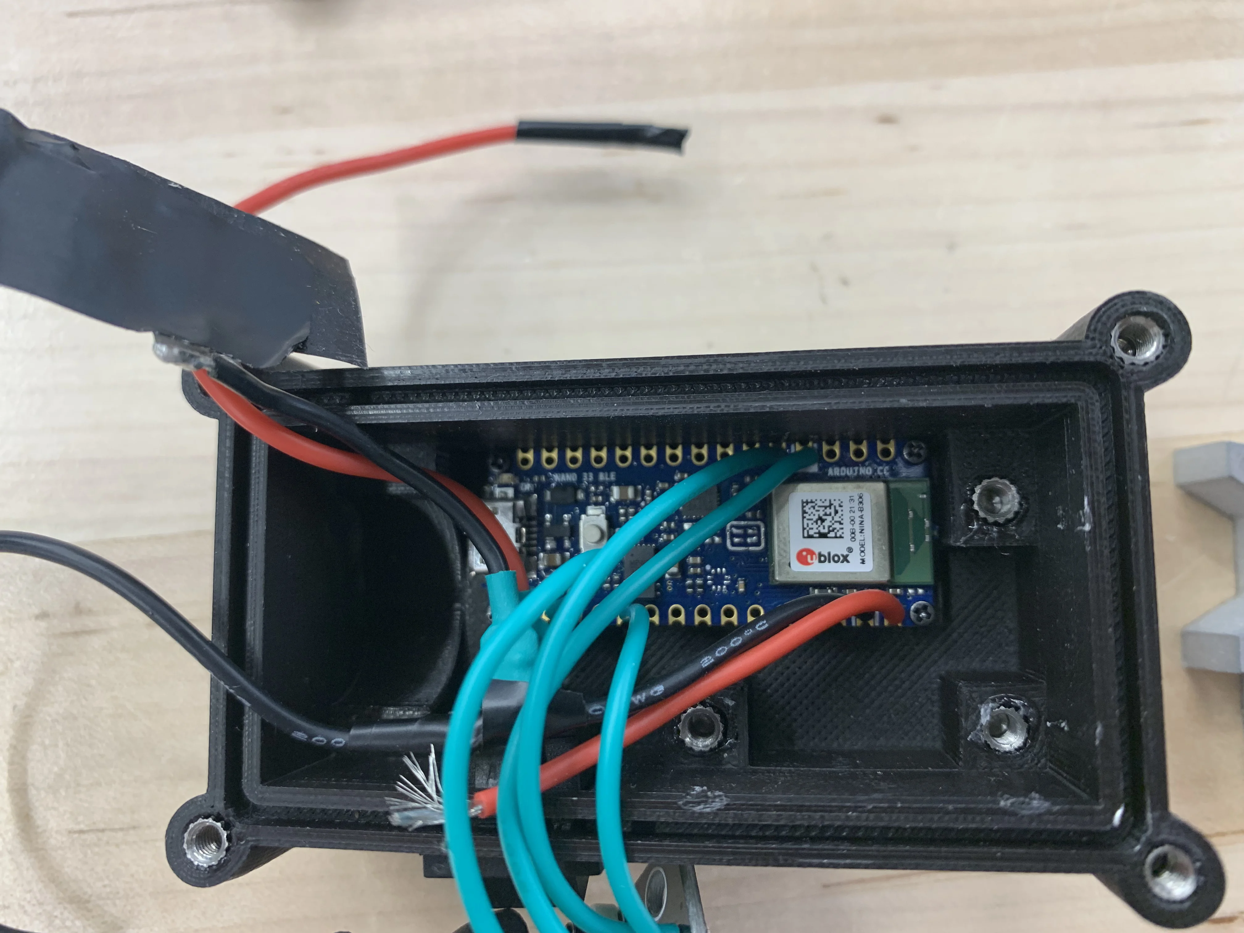
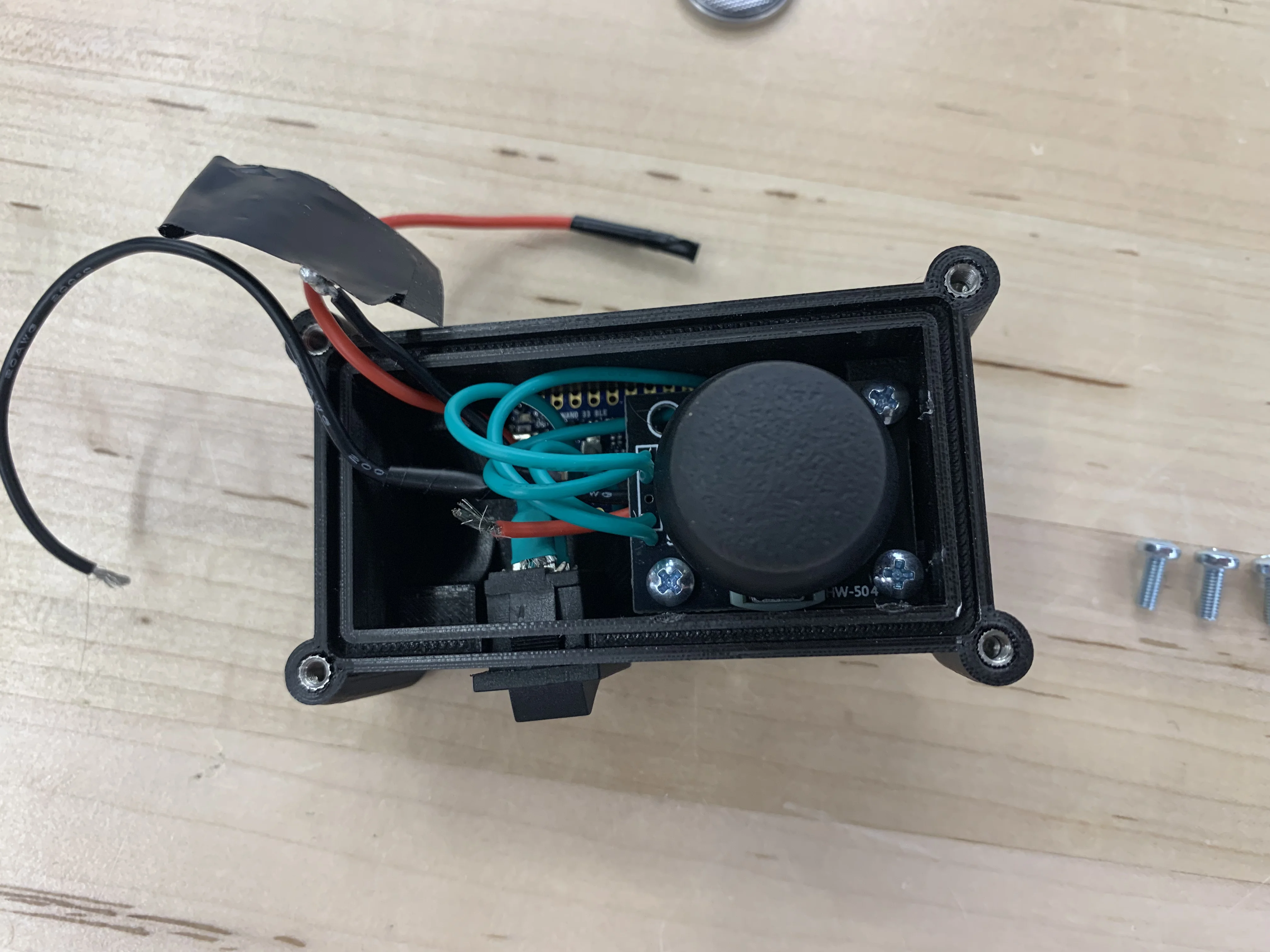
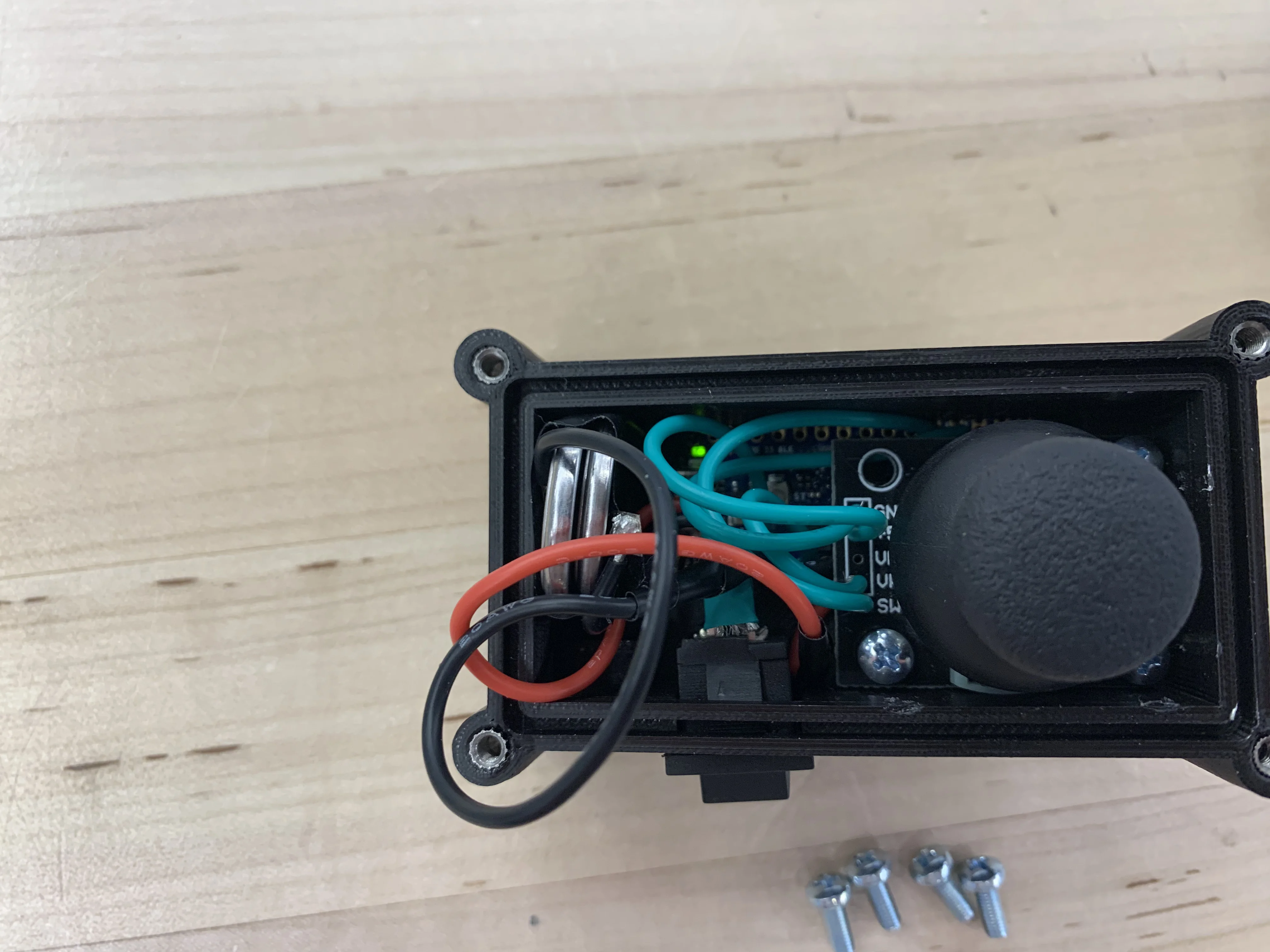
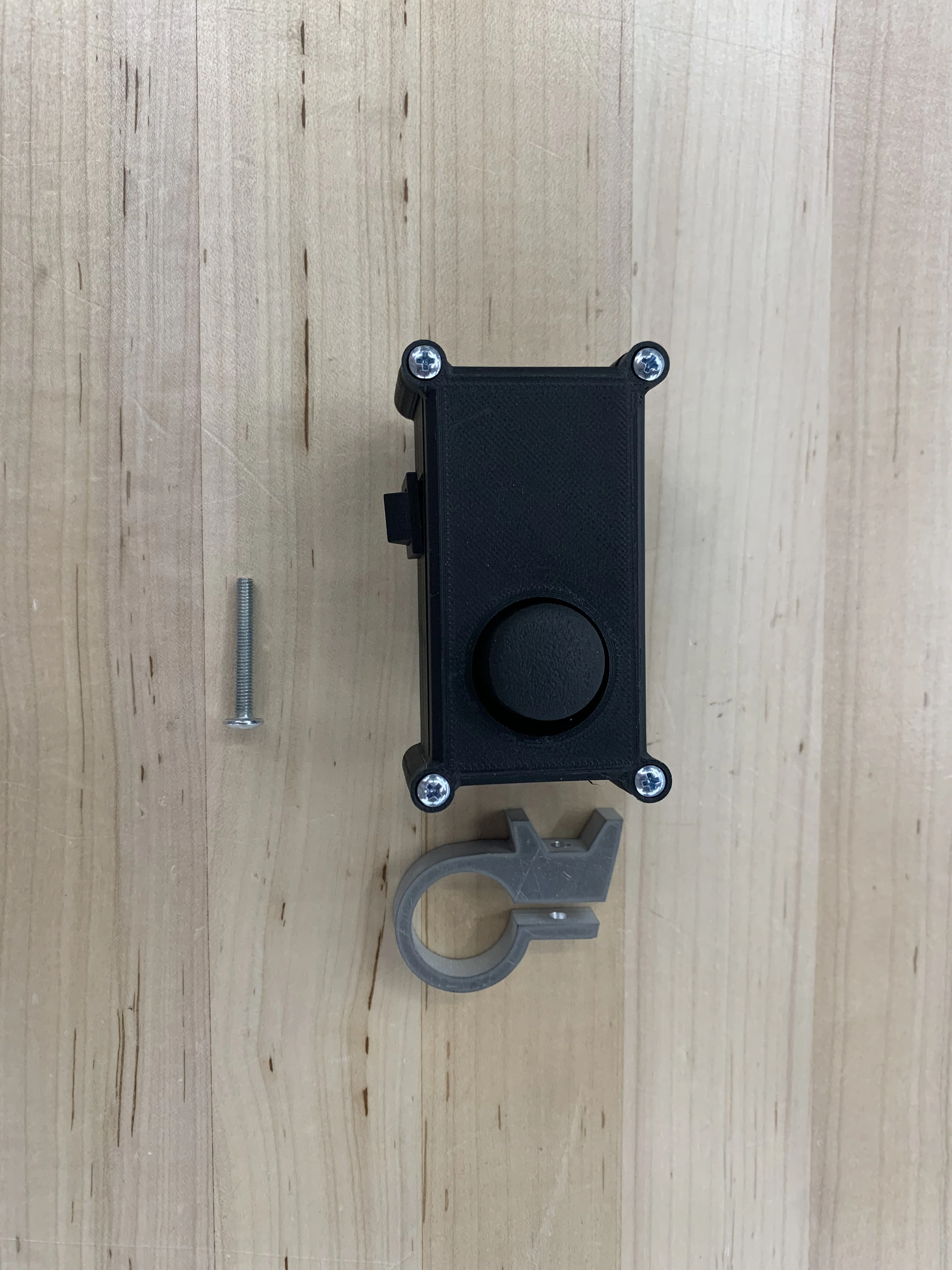
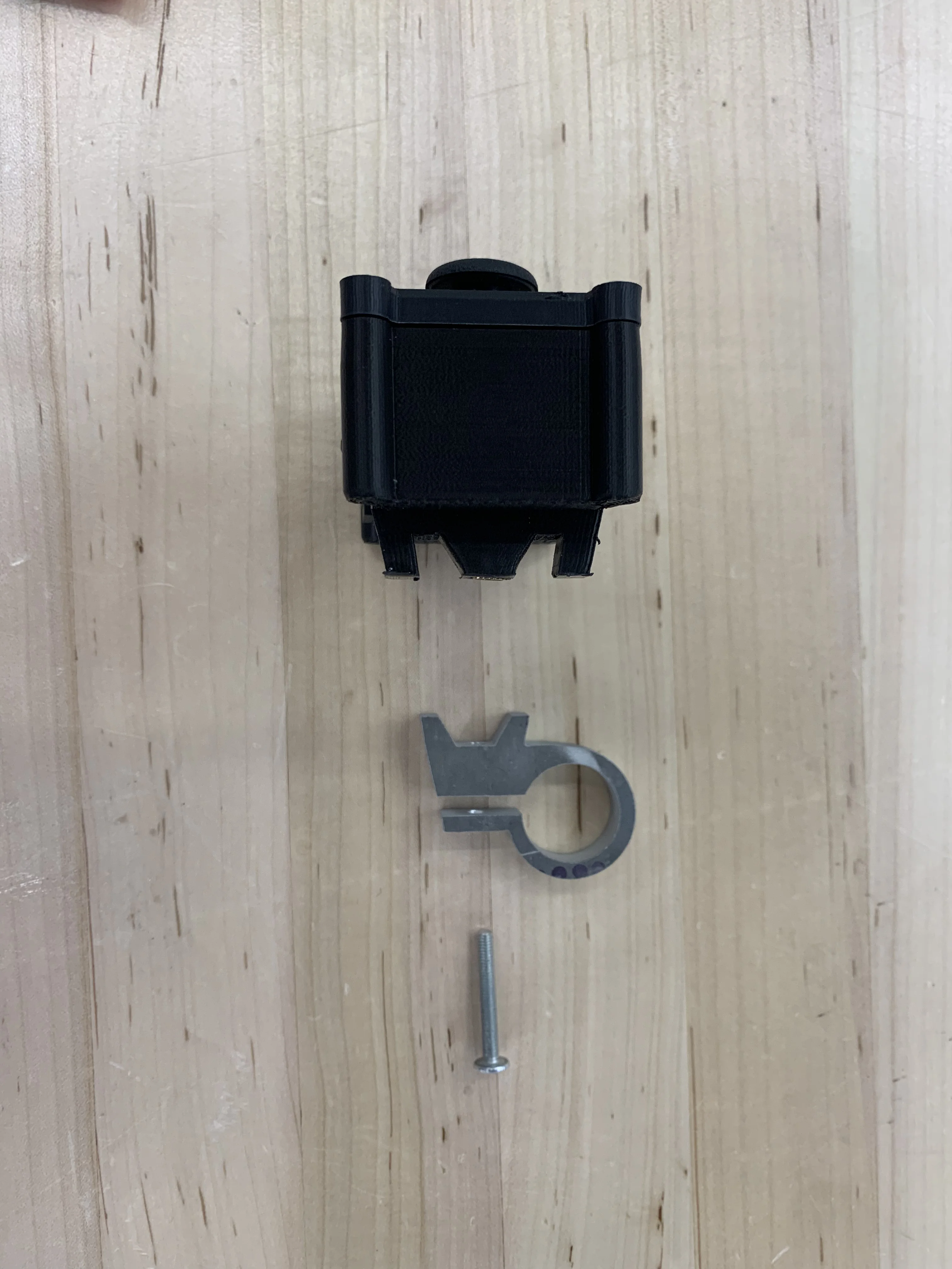
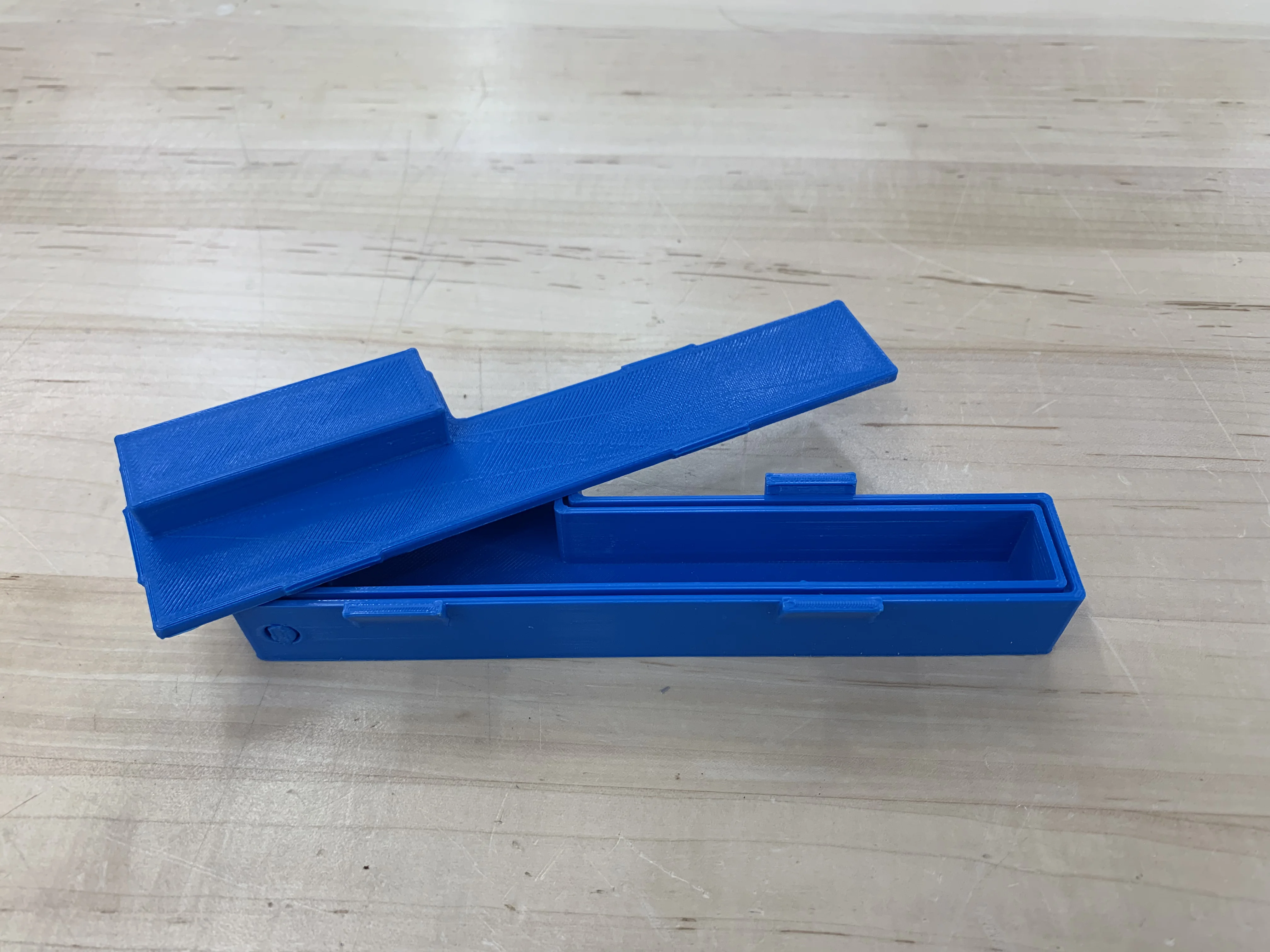
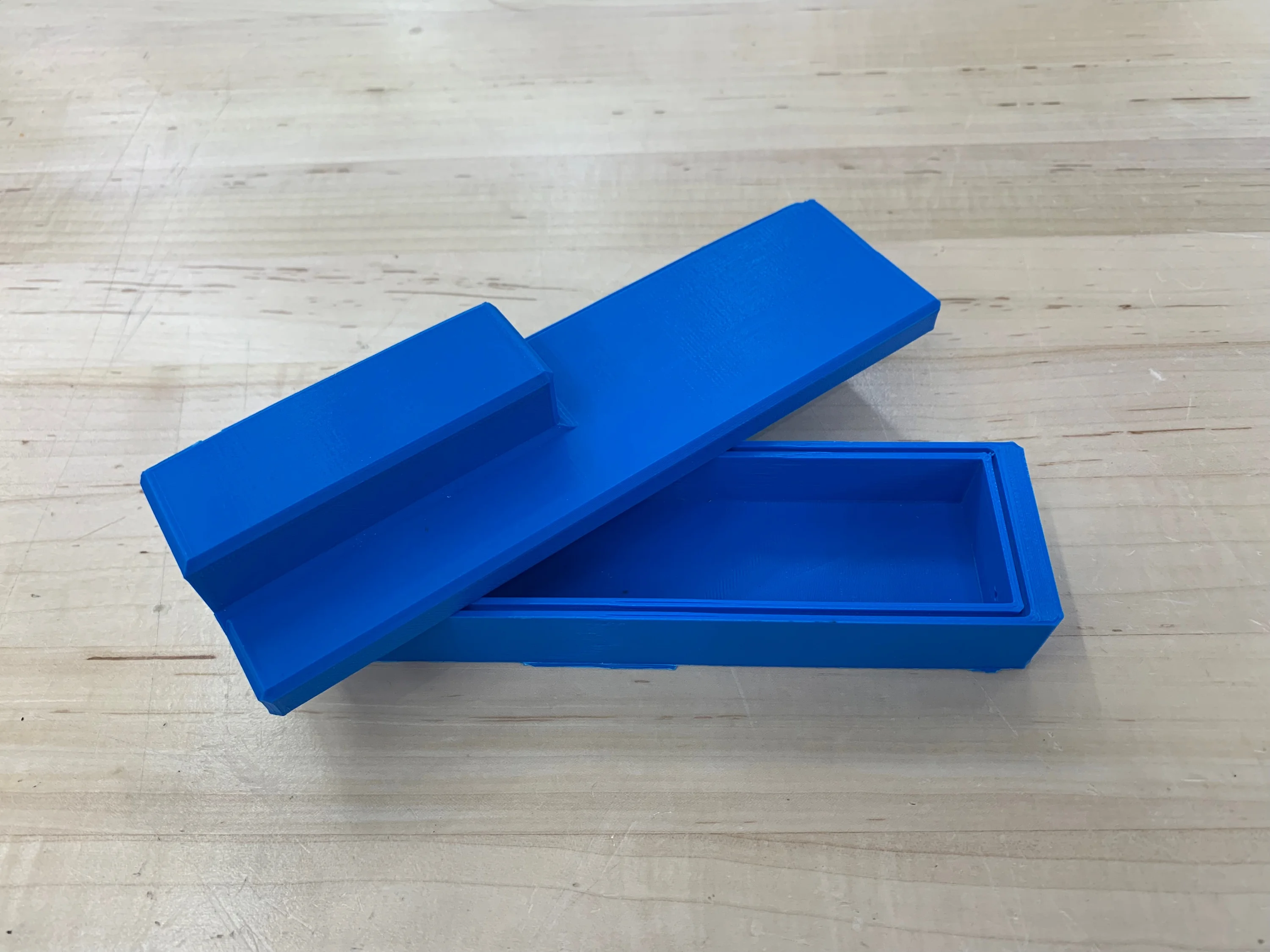
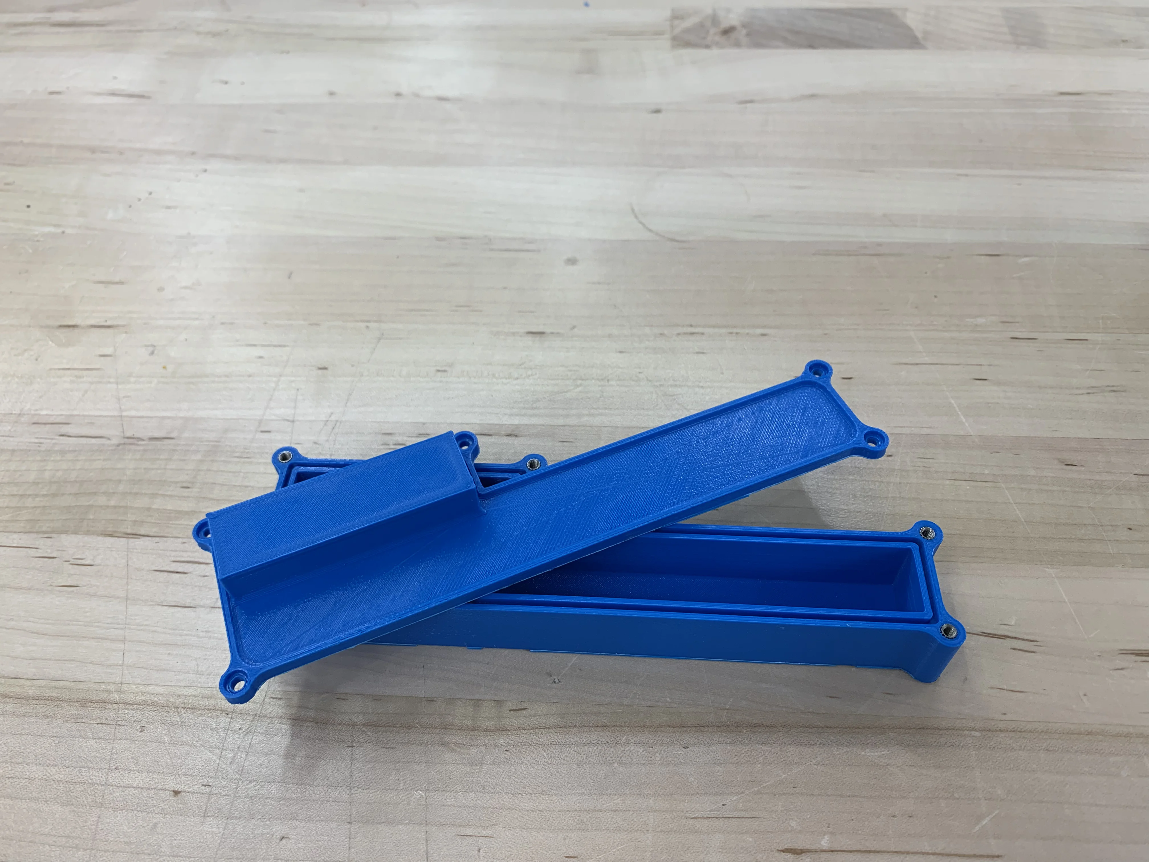
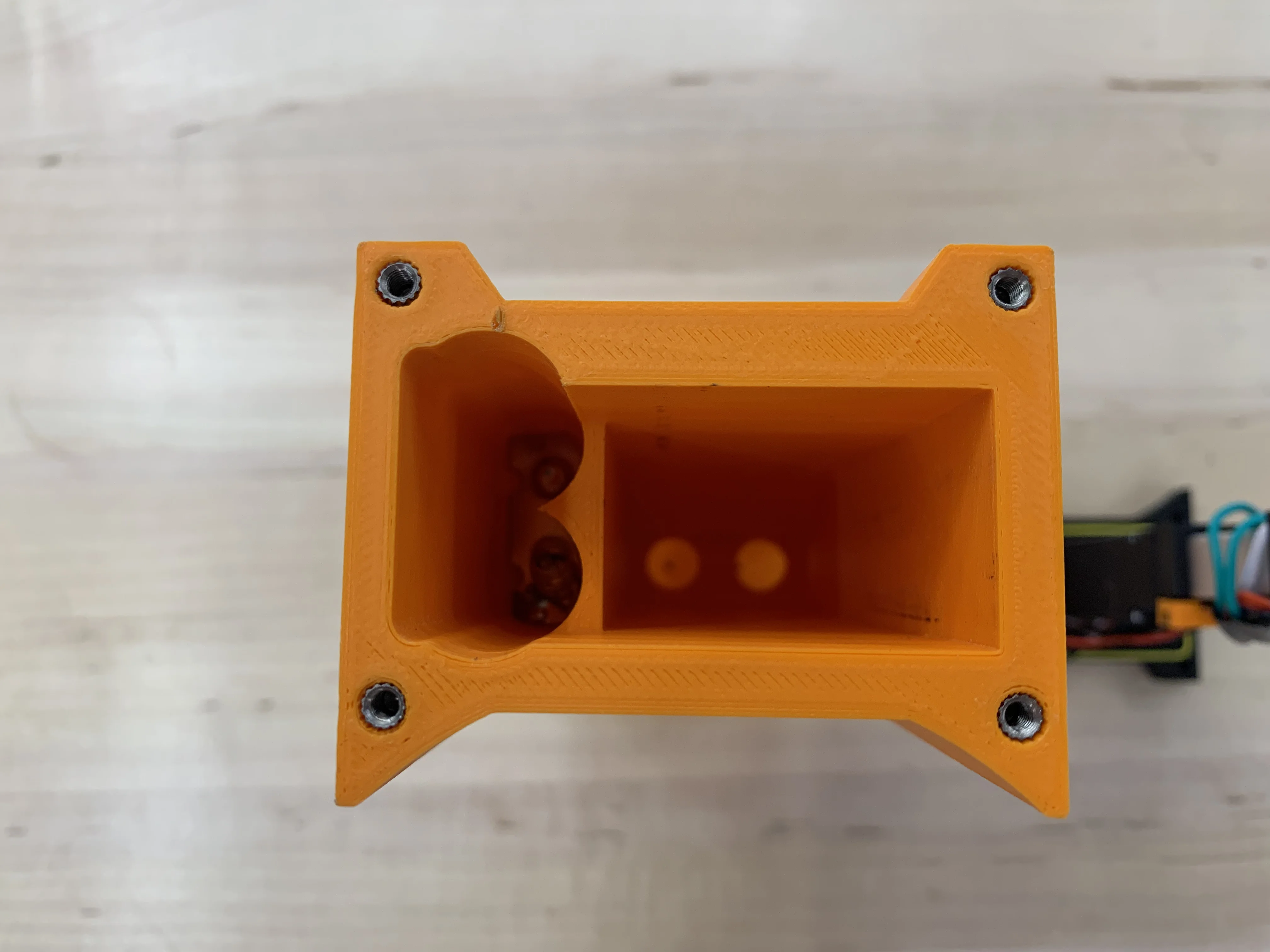
First, I designed 3 different housing closure types: snap fit, press fit, and a bolted version. This was motivated by the user need to easily access the batteries. I ended up designing around the bolted style enclosure because the vibration tests I performed proved fatal to the snap fits that I made.
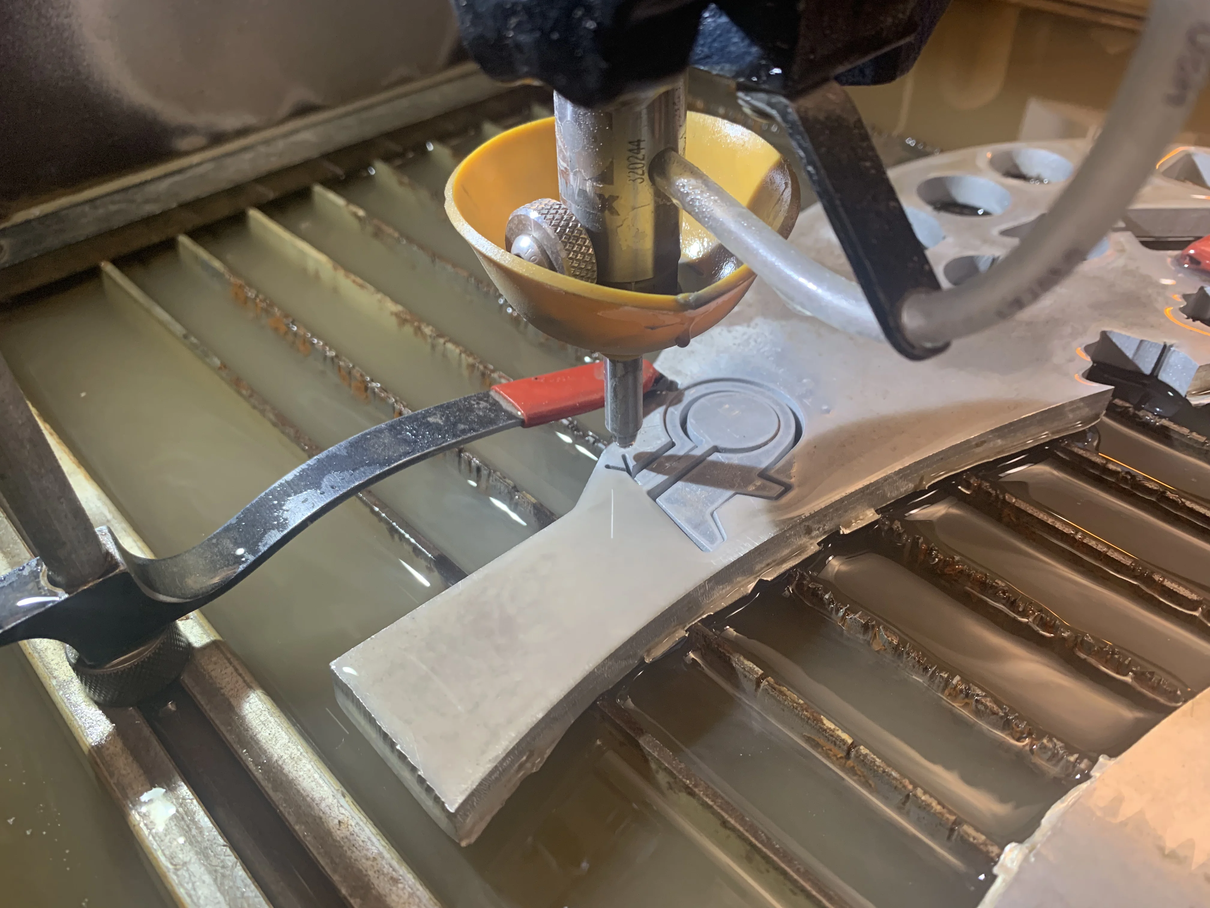
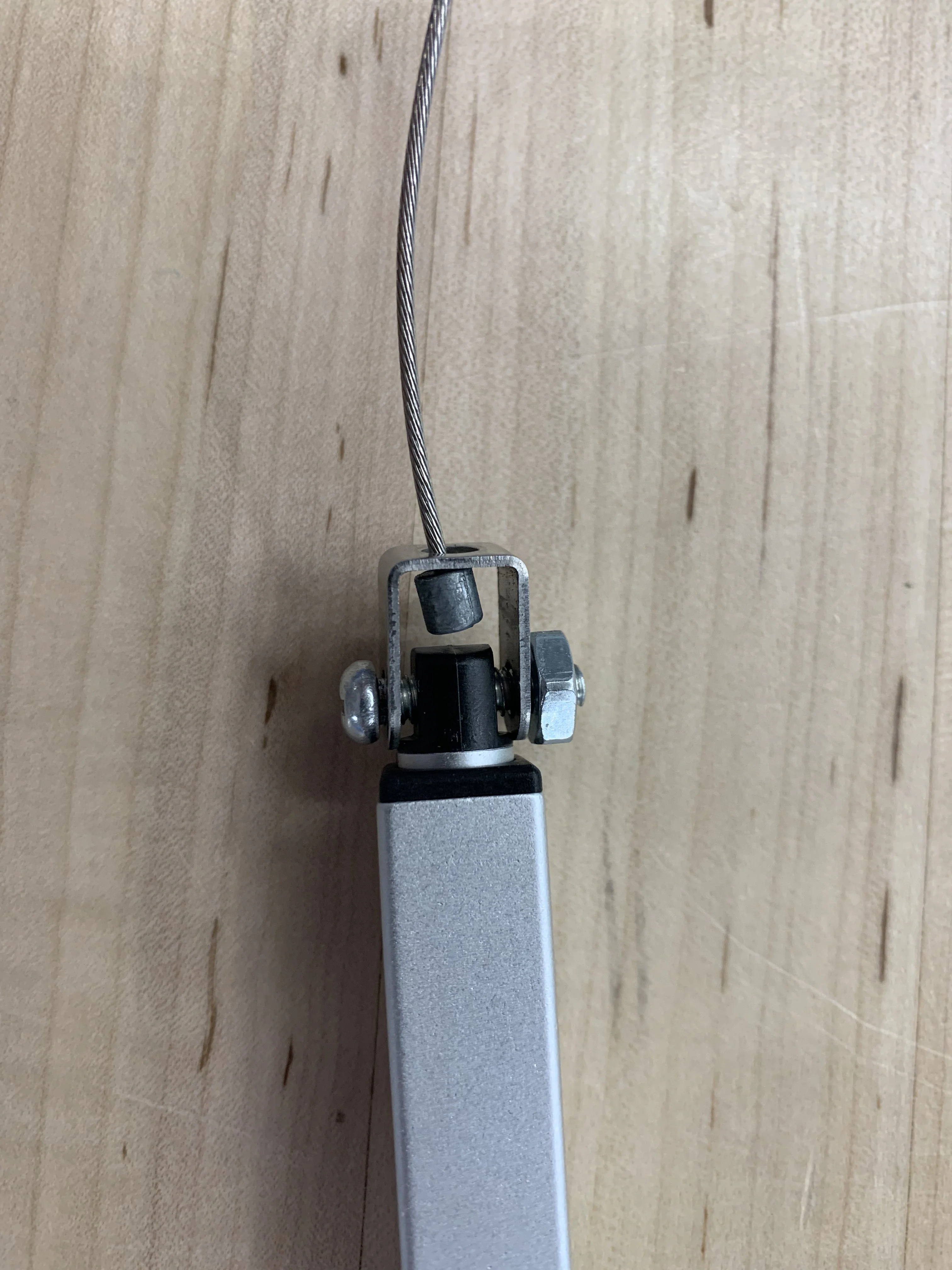
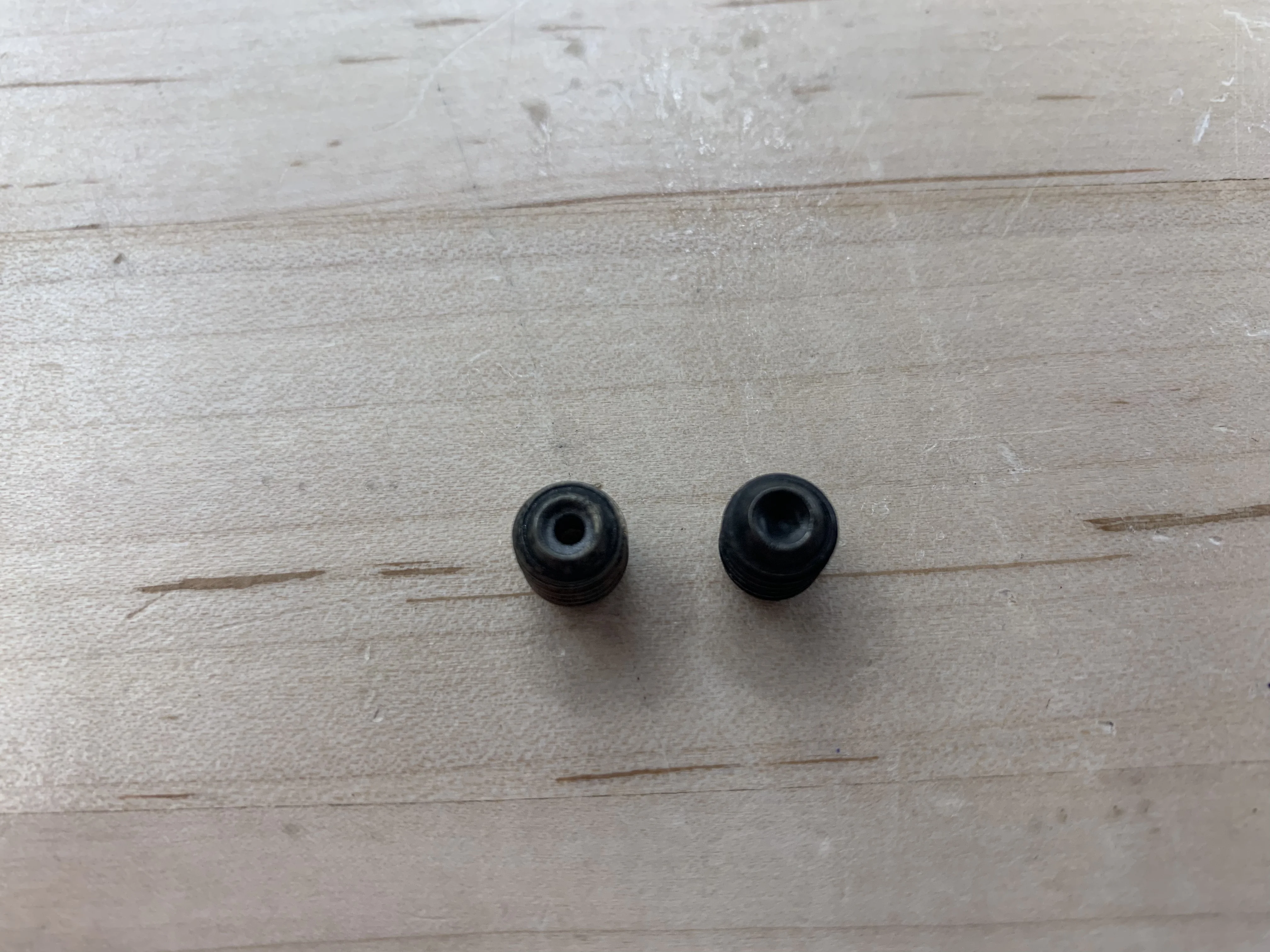
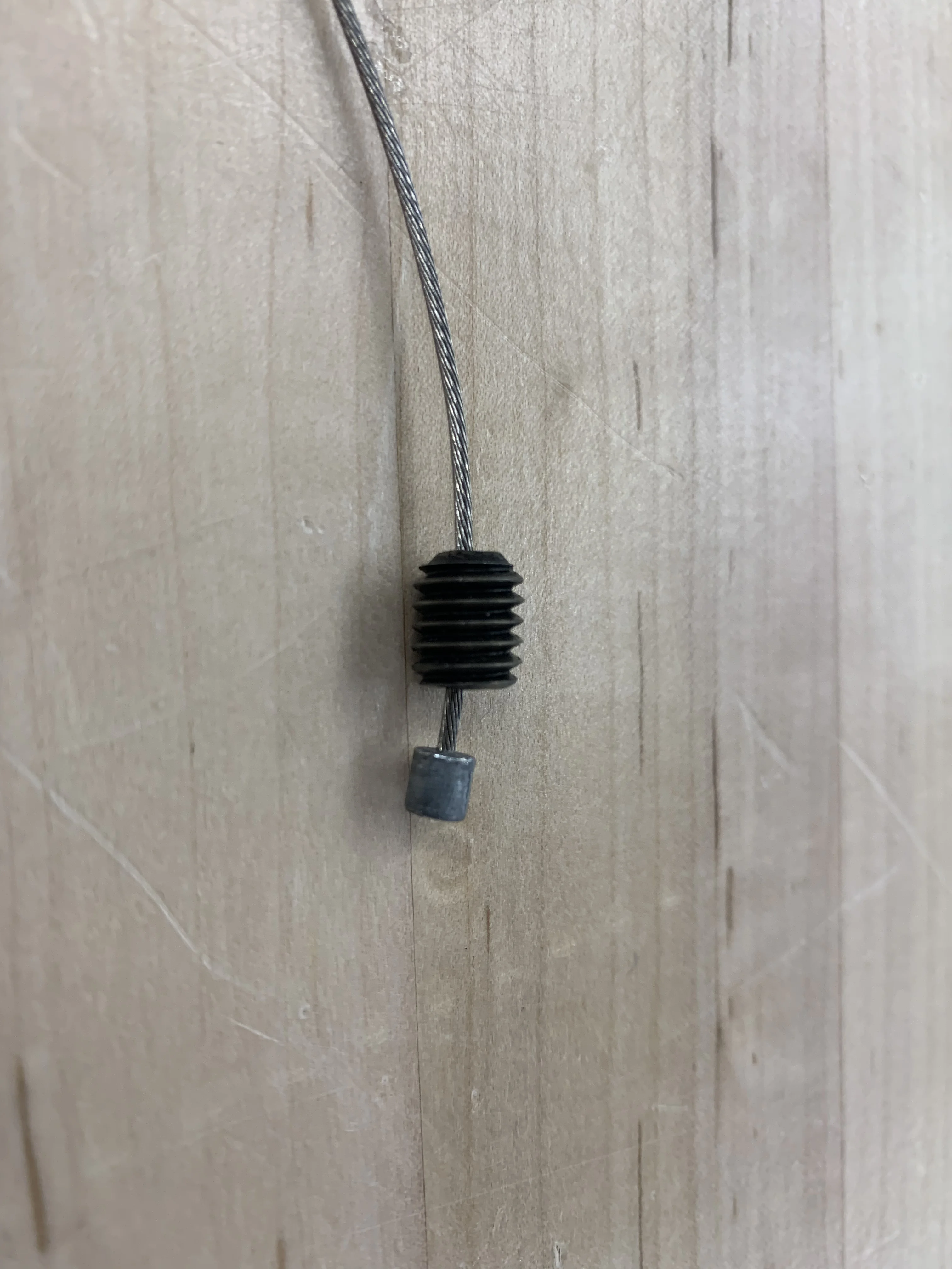
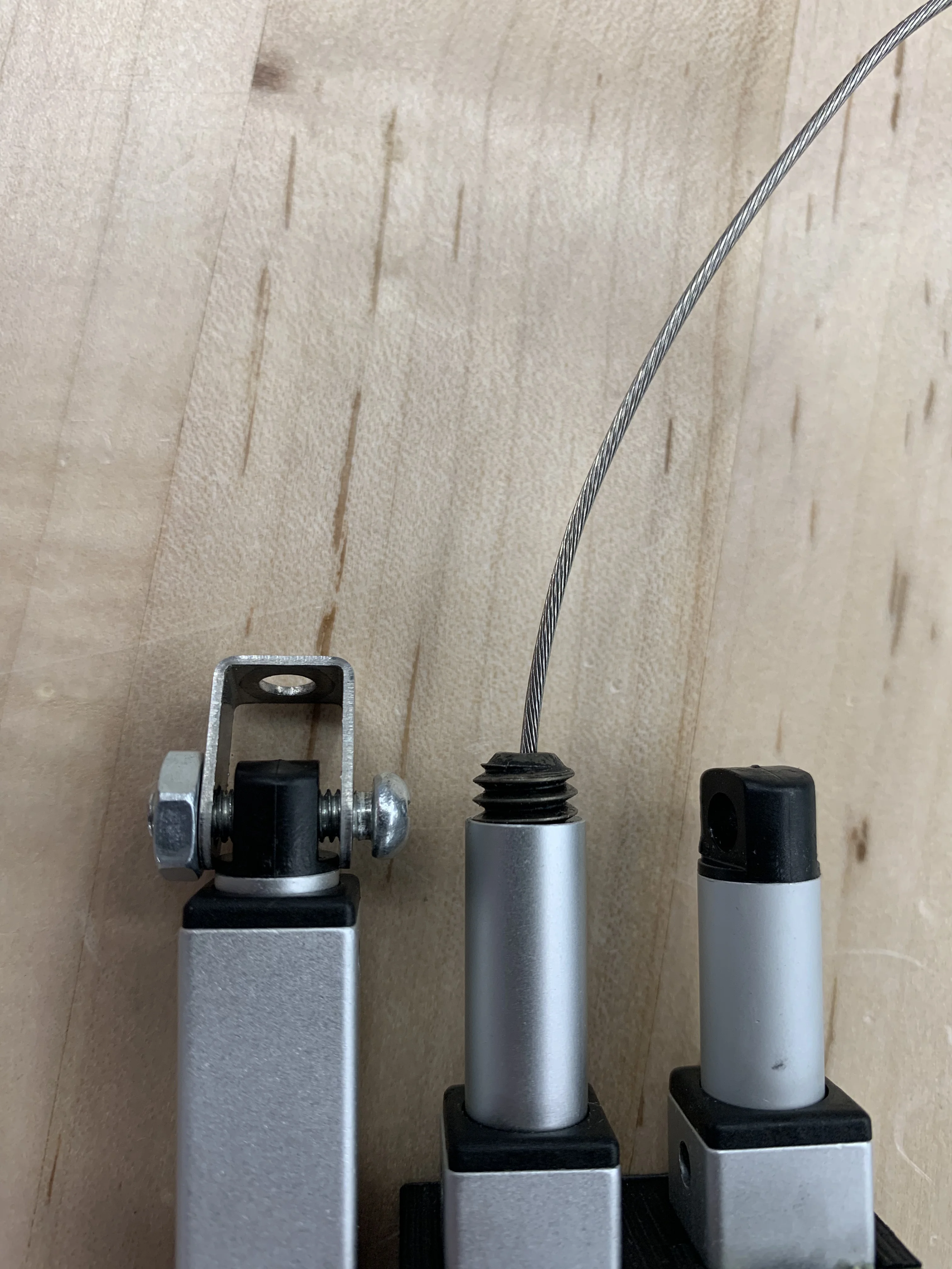
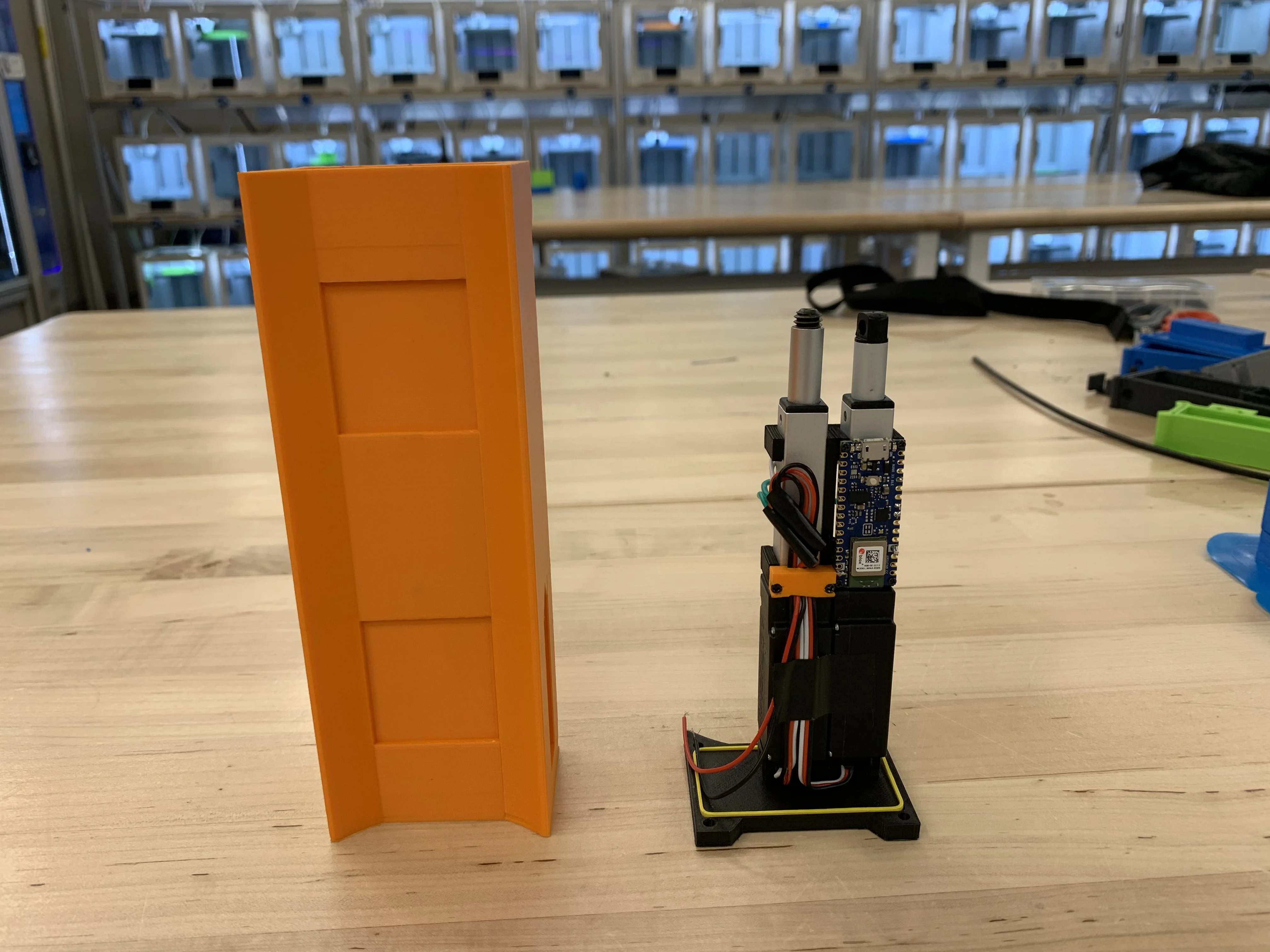
Another challenge I ran into while designing the reciever housing were the size limitations of the 3D printers I had acess too. I needed the full stroke of the actuator to accomodate for all shifters, but this full length with the housing was slightly too large to fit in any printer. In order to shorten the overall length I realized I could shorten the cable and actuator interface. To do this, I modified a set screw rather than machining or 3D printing a complex part.
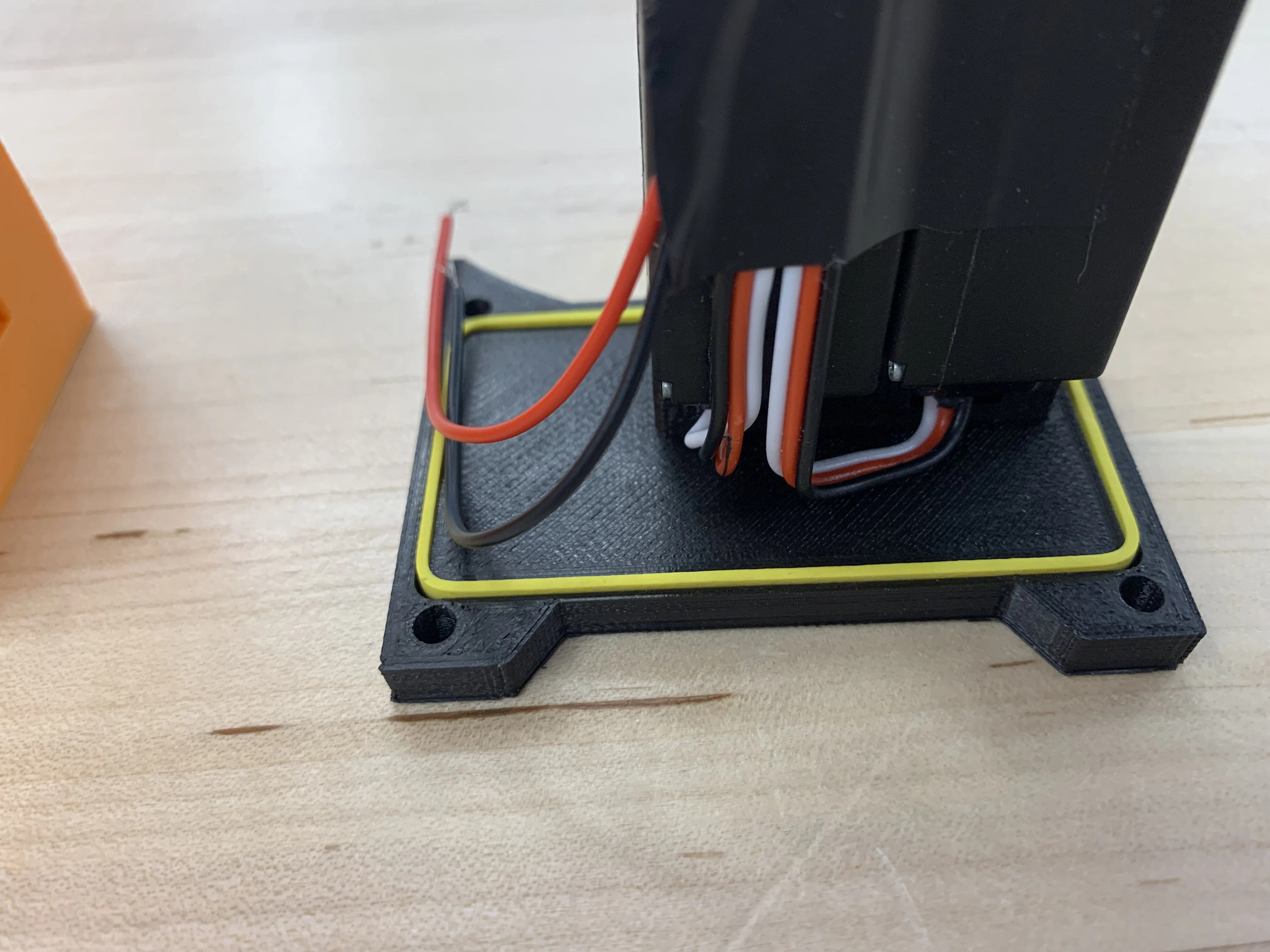
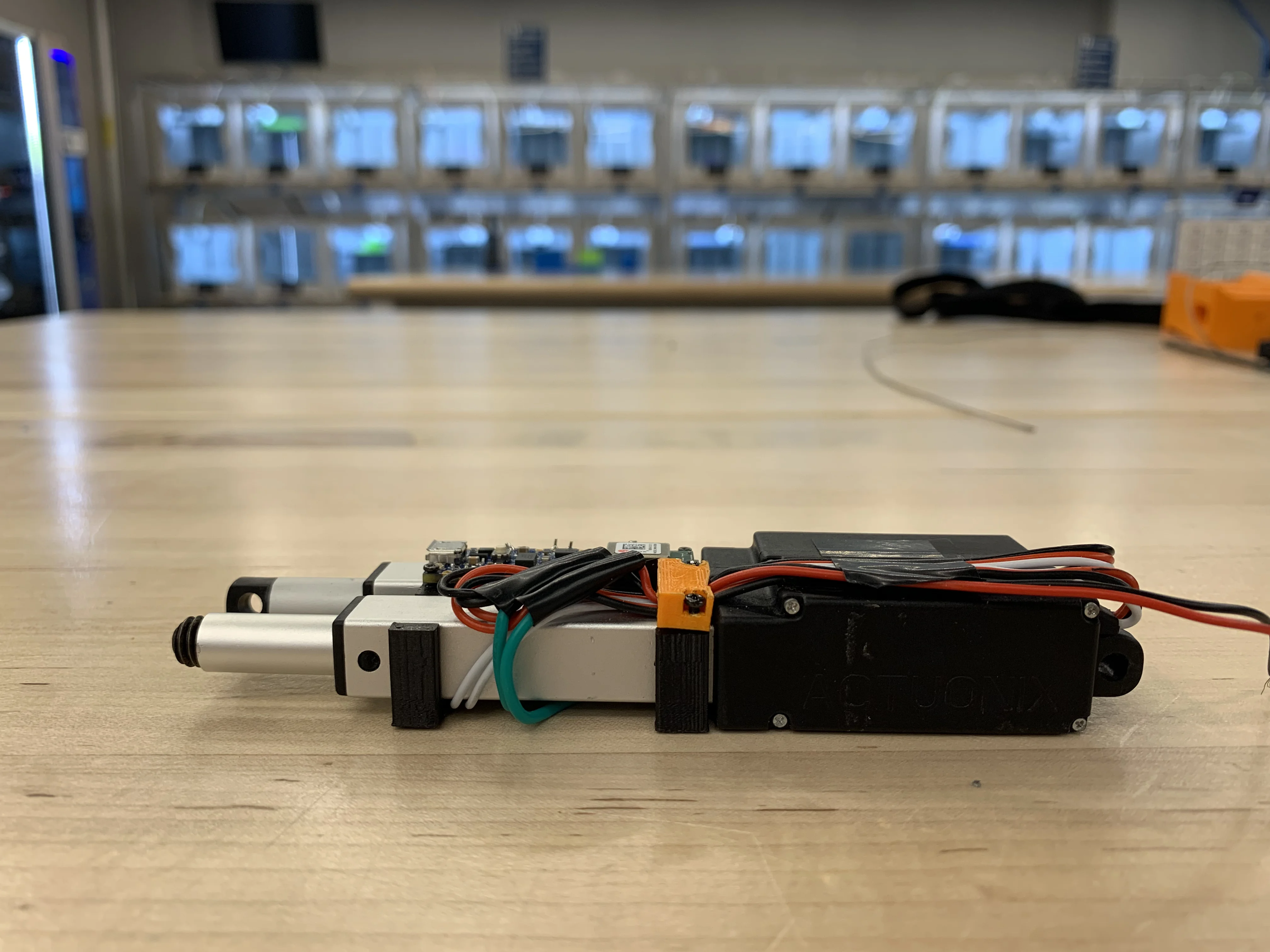
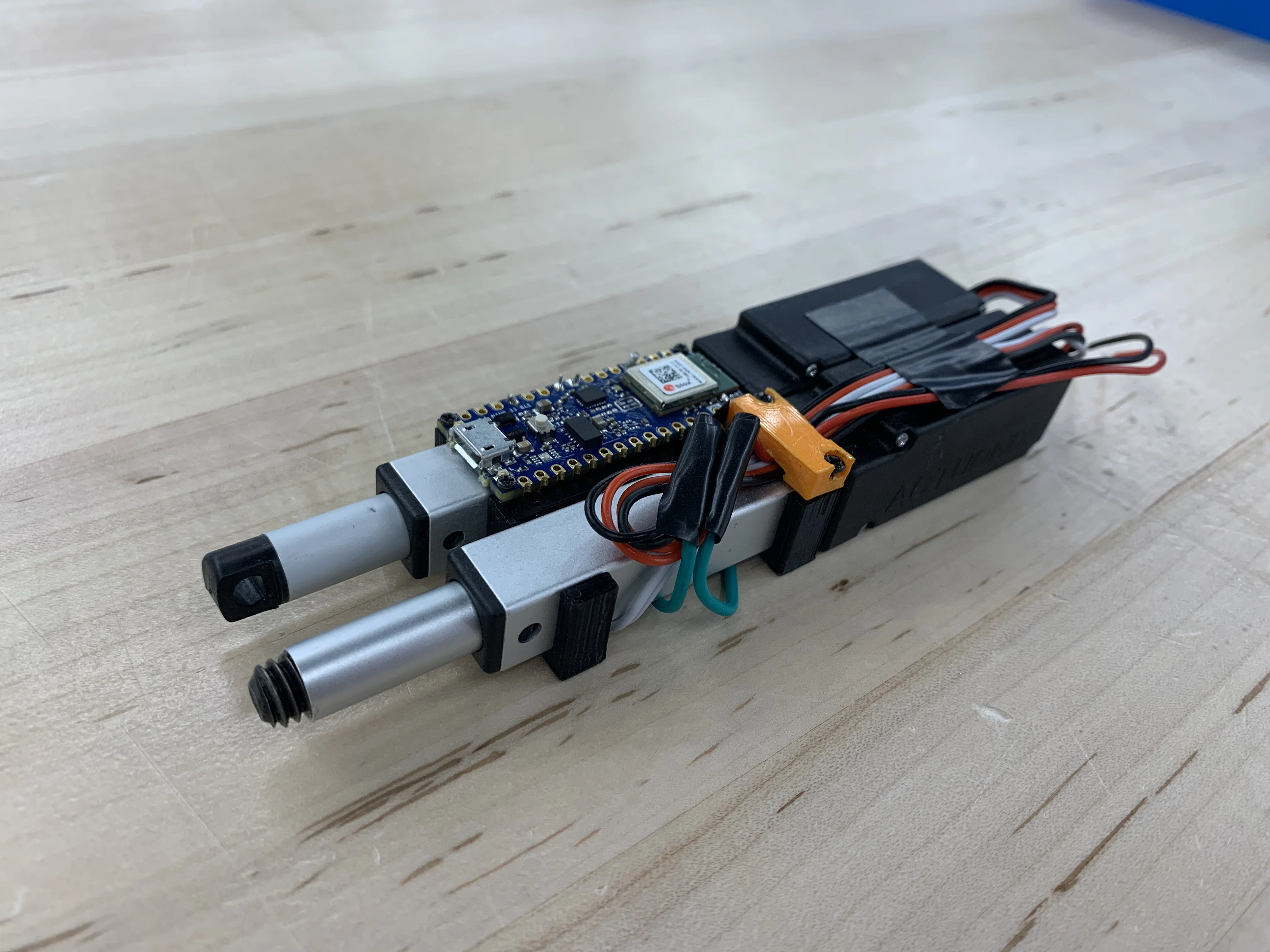
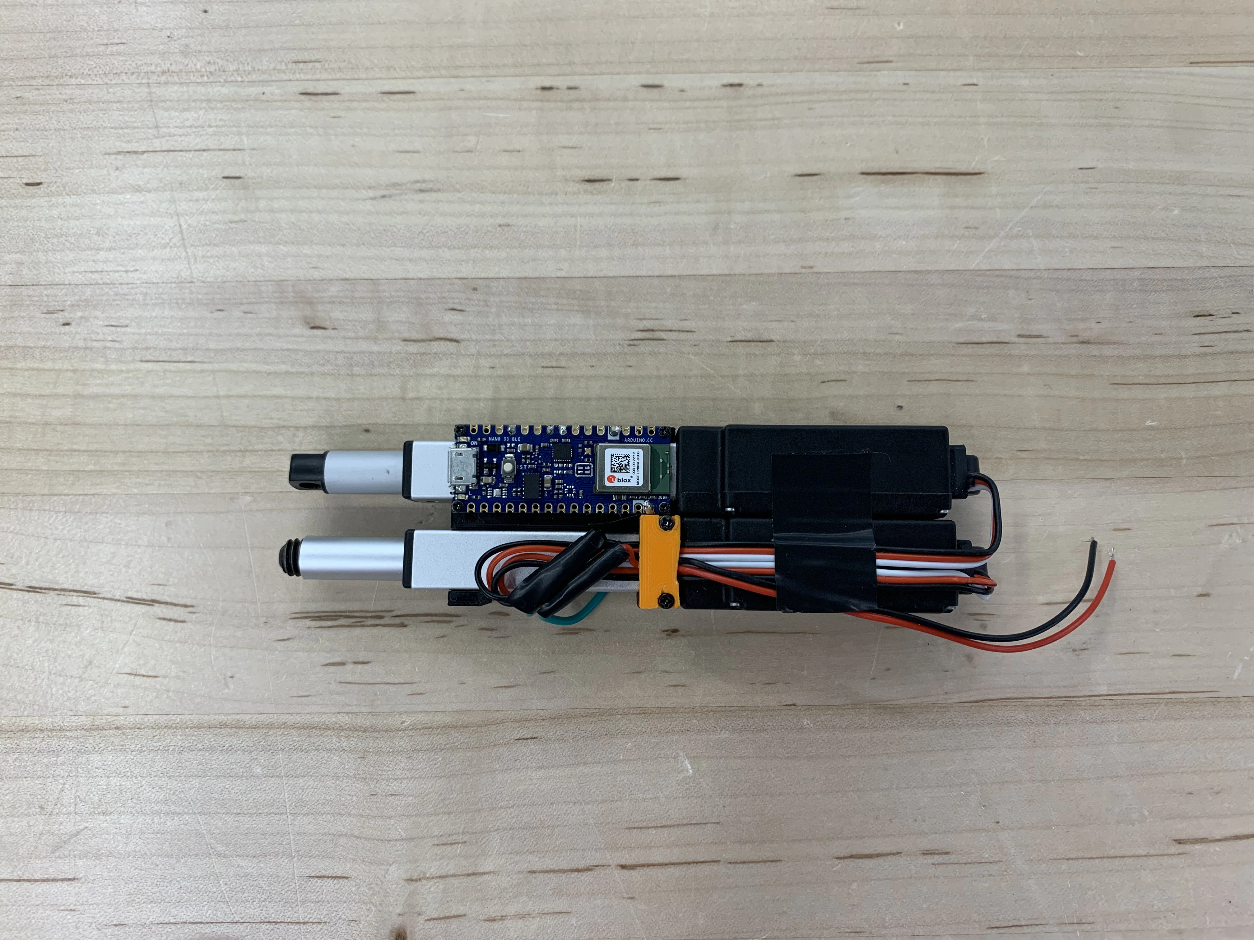
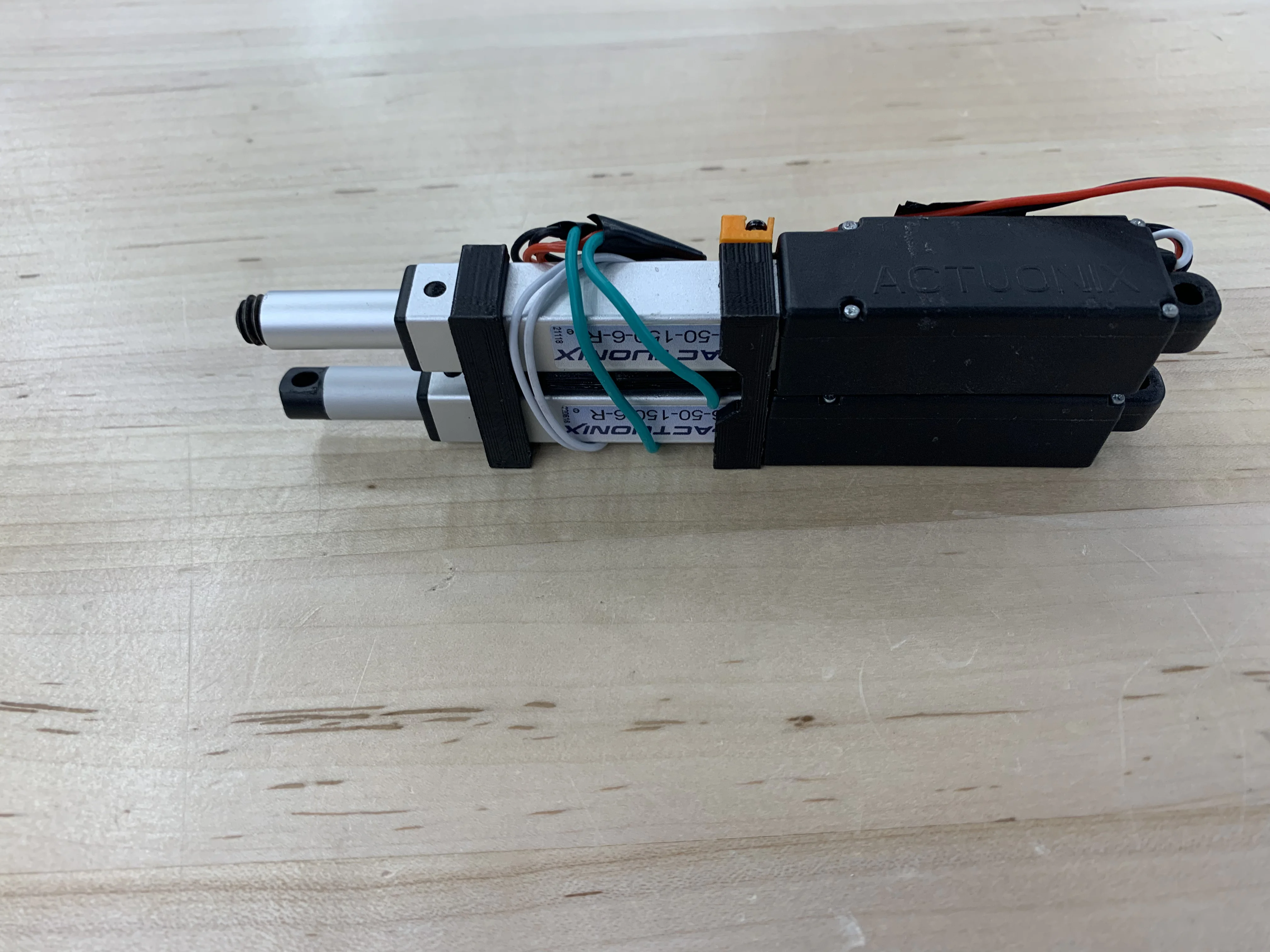
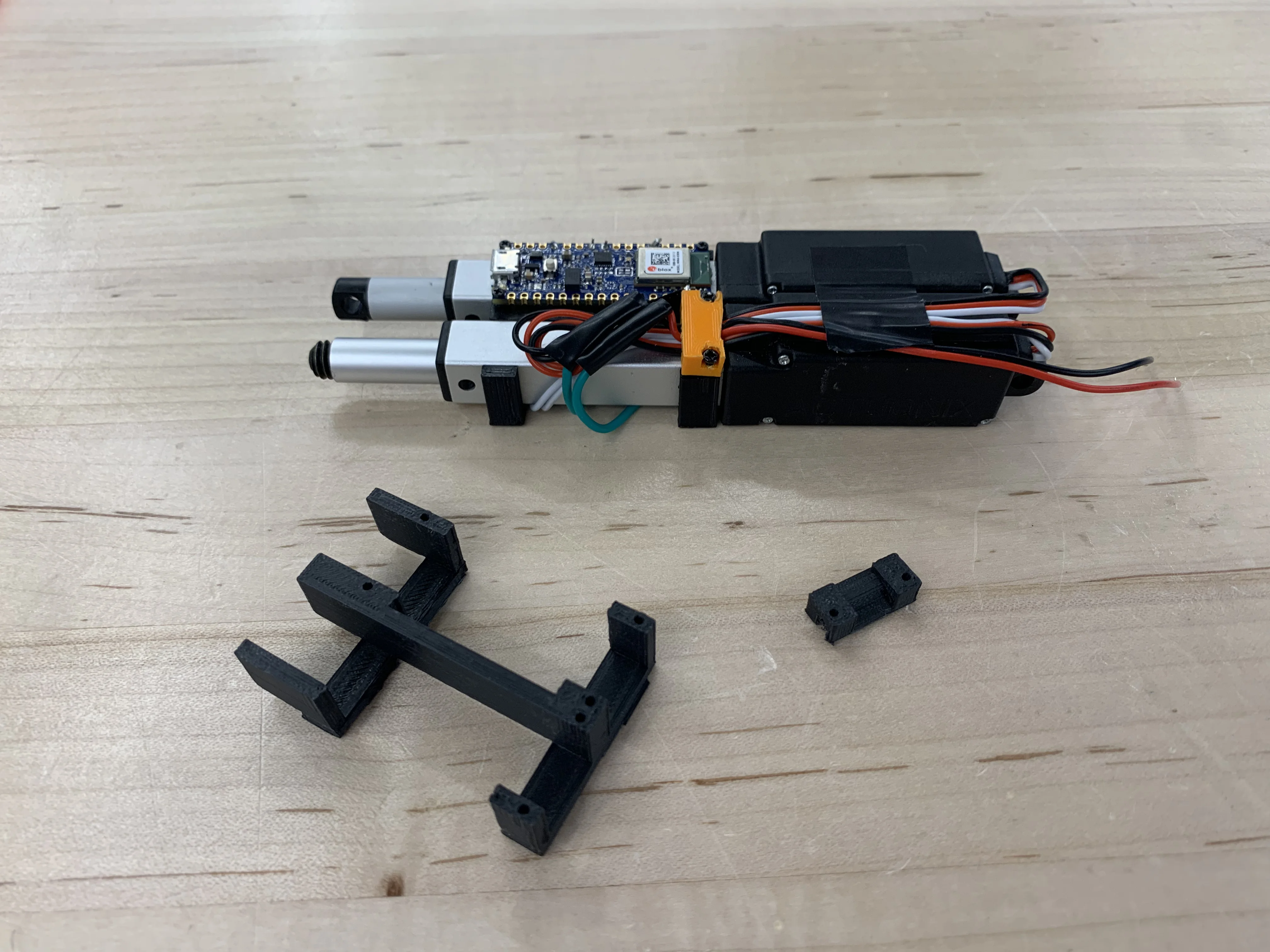
After talking through my design decisions with an upperclassmen engineering student, I realized that it might be much more effective to minimize the seal area by moving the seal to the rear of the device. With the redesign I also decided to include an additional actuator, increasing the functionality to not only converting the shifter to bluetooth but also the dropper post. A key element of this redesign is the actuator harness. It organizes the wiring, holds the actuators in place, and provides a place for the Arduino Nano to be mounted.


It is quite hard to visualize the control loop of this system without a block diagram. The input is obviously the desired gear and the output the actual gear

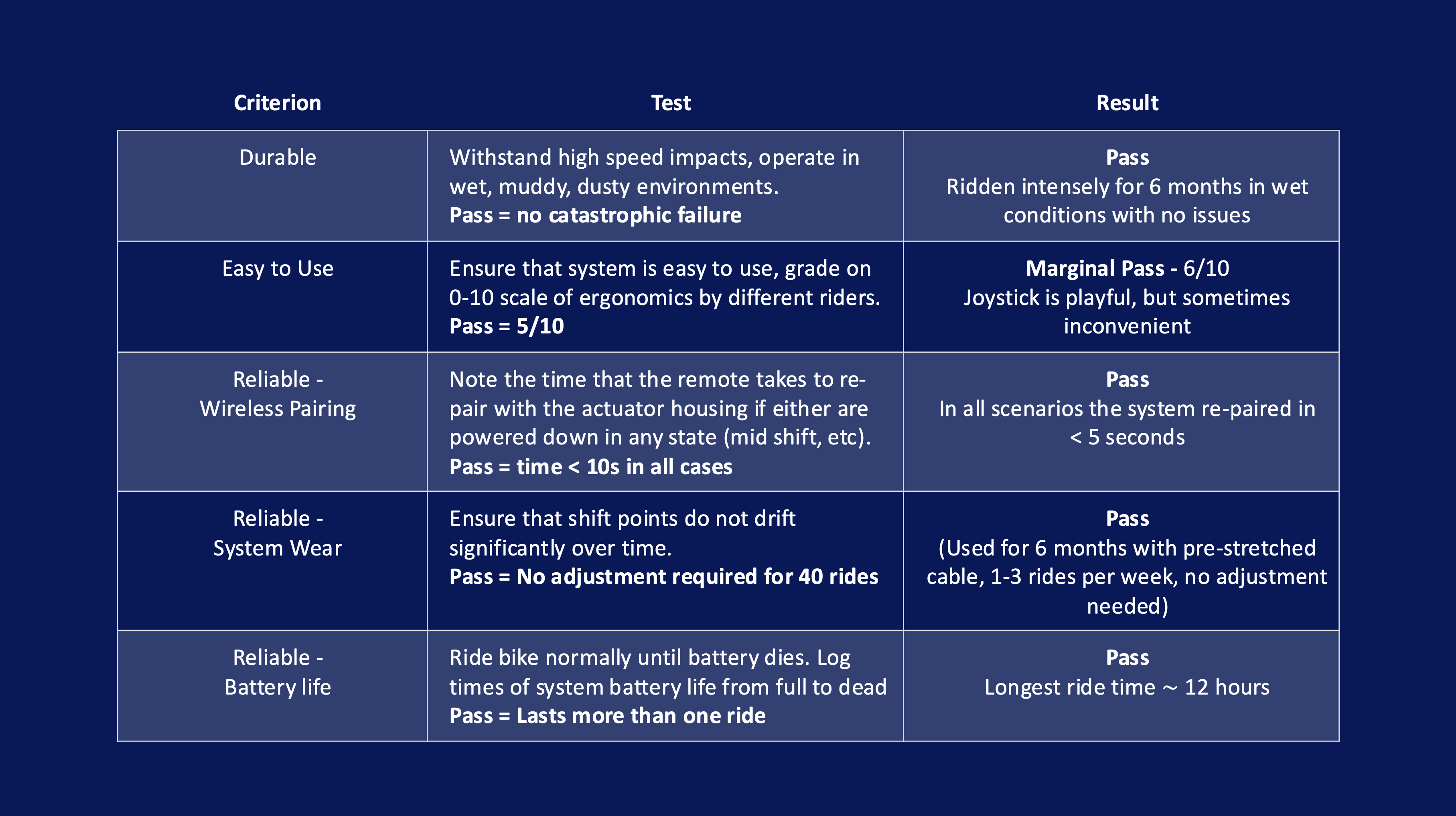
Throughout the course of this project various tests were performed to quantify the device such as a battery life test, bluetooth connectivity test, ingress testing, and most importantly a rigorous validation field test for 6 months.
One of the more uncertain parts about this project were the shock loads that the device might experience. Instead of devising a way to estimate and test shock loads I went straight to testing on high speed impacts such as the jump shown to the left.
Other tests conducted throughout the development process are documented in the table below. A highlight of these results is that the shifter did not require adjustment over 6 months of riding.
